Photograph 1 of 83
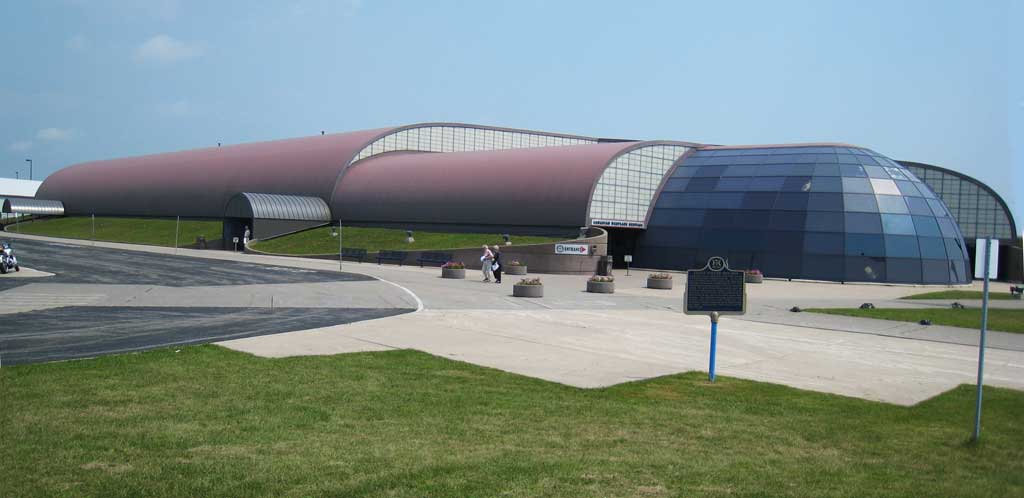
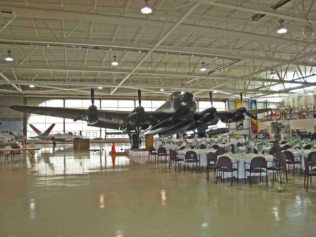
We're here to see the inside of their Lancaster bomber (which was the type of aircraft piloted by Clifford Shnier).
At this early hour (9:15 am on a Saturday), there are already over 50 cars in the parking lot – all members who are volunteers and pay to work on restoring the aircraft.
The museum has an annual budget of over $3,000,000, and less than 1% of this comes from the government – they are self-supporting through membership dues, their educational program, a summer camp program, admission fees, a gift shop with excellent posters and DVDs, and fees for guests to fly in the aircraft ($2,000 for the Lancaster).
Photograph 2 of 83
Photograph 3 of 83
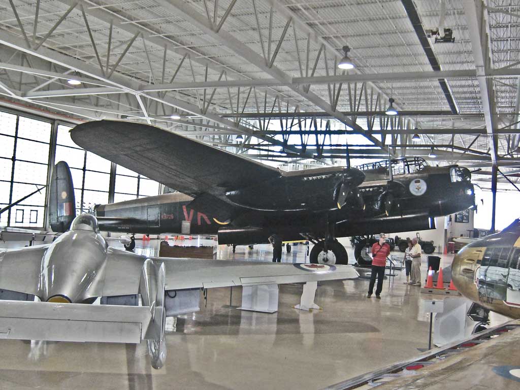
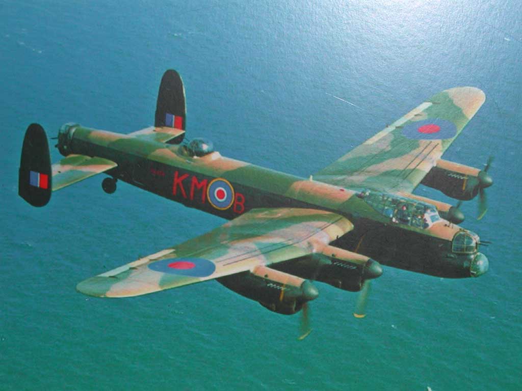
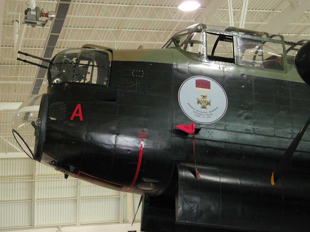
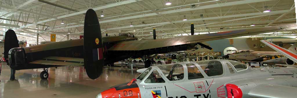
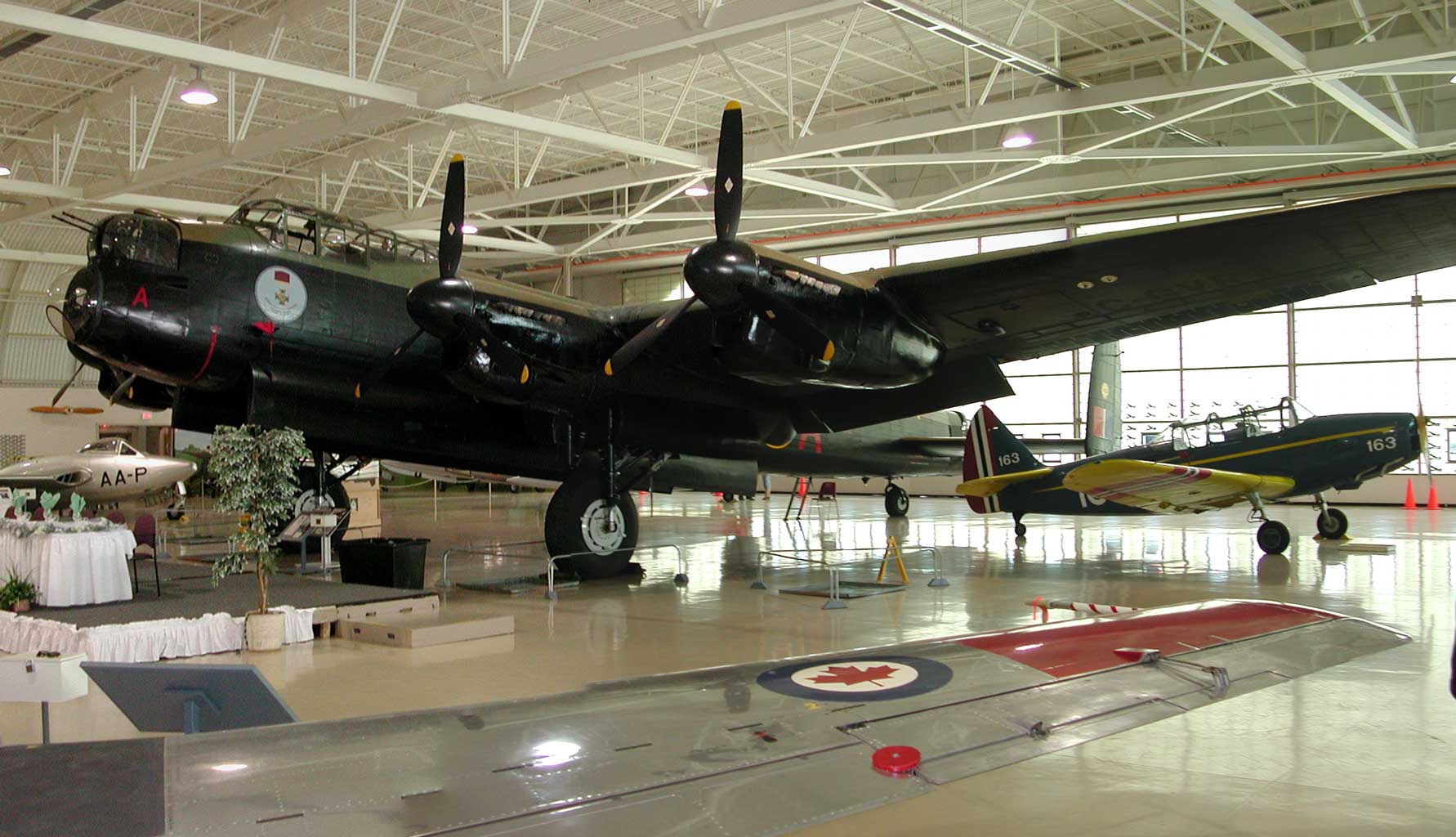
There are now only two Lancaster bombers in the world that are in flying condition, and this is one of them (the other is owned by the RAF in the UK, and the public isn't allowed into it).
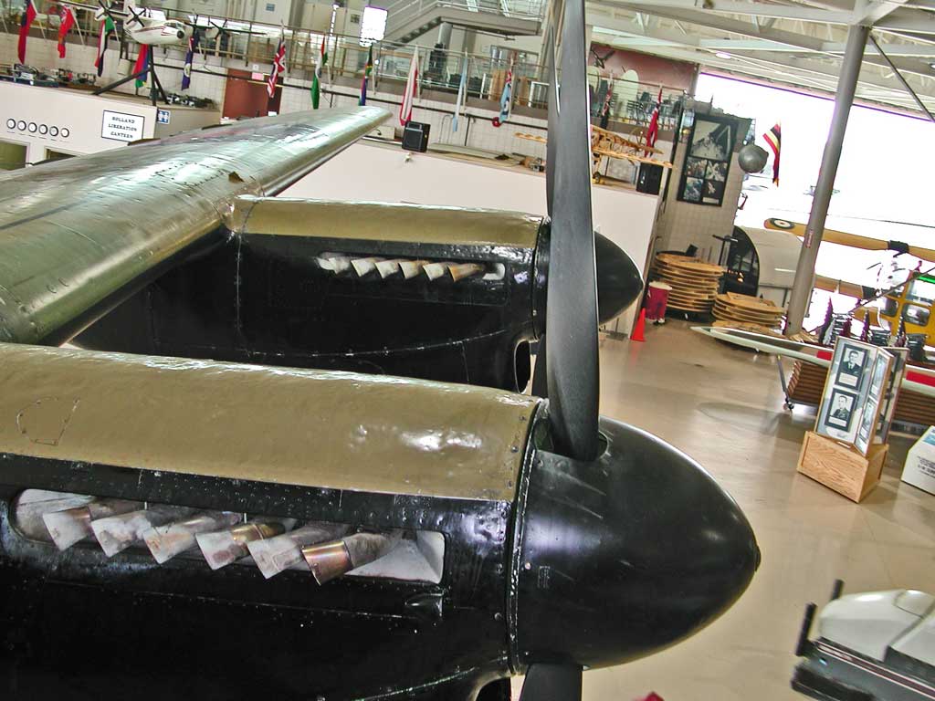
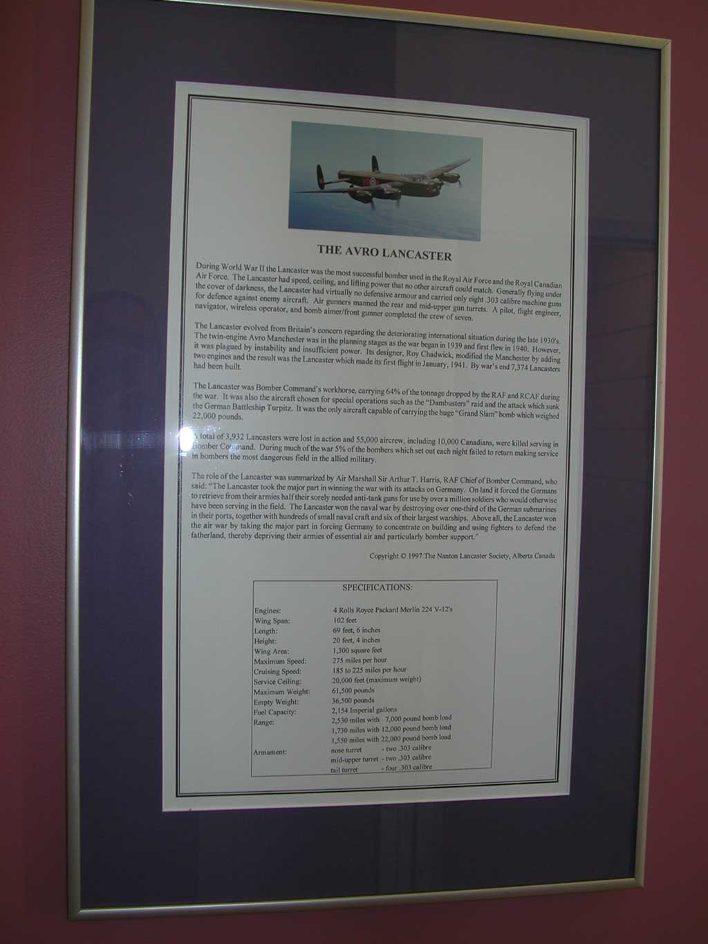
This is the largest airplane in the Museum's collection, and some information is here.
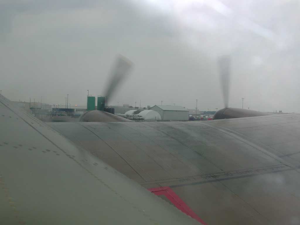
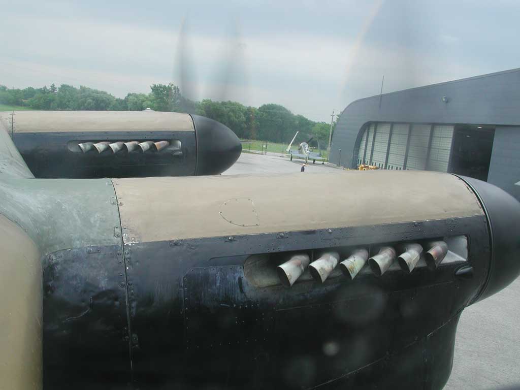
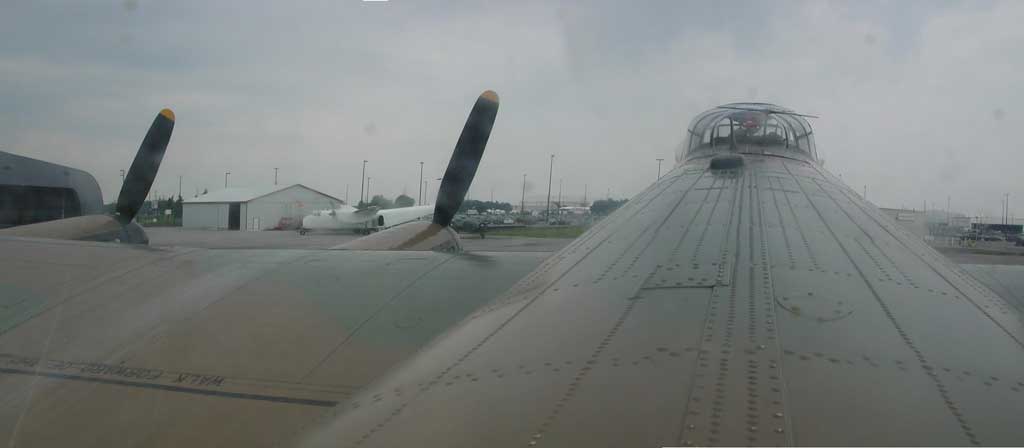
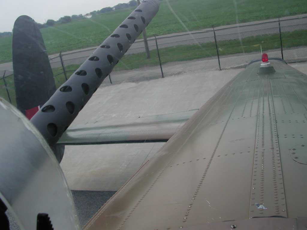
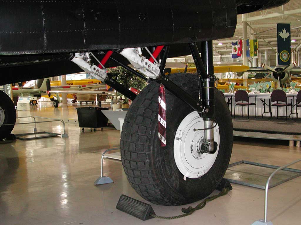
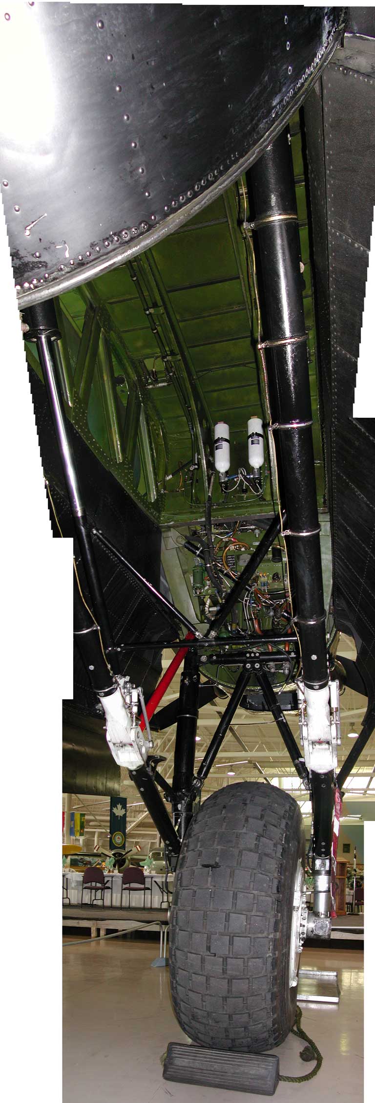
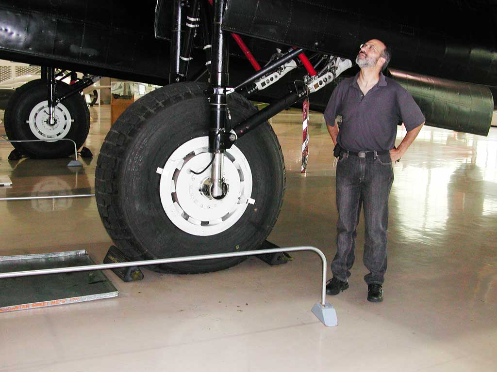
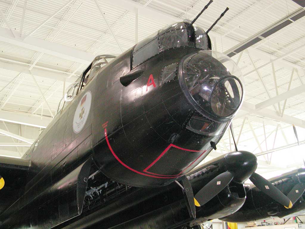
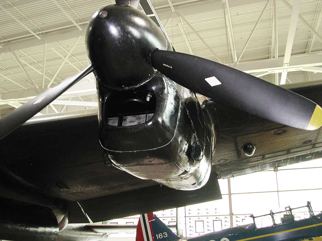
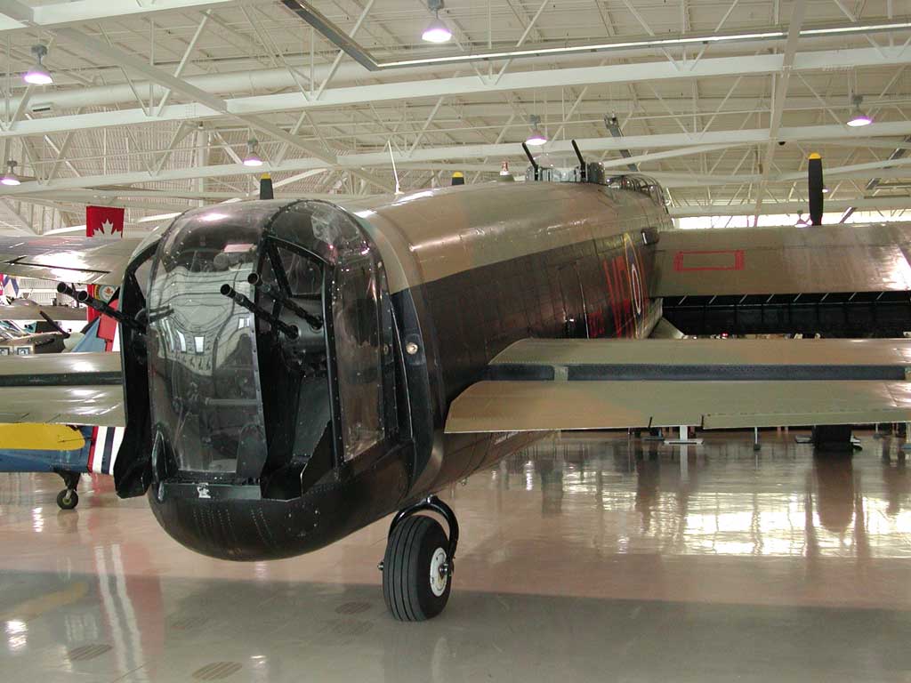
In this photograph, you can see two of the four 1,460 horsepower engines, the huge wheels, and the two front .303 Browning machine guns, which were operated by the bomb aimer who usually would lie prone, looking through the perspex cupola below them.
Photograph 4 of 83
Photograph 5 of 83
Photograph 6 of 83
Photograph 7 of 83
Photograph 8 of 83
Photograph 9 of 83
Photograph 10 of 83
Photograph 11 of 83
Photograph 12 of 83
Photograph 13 of 83
Photograph 14 of 83
Photograph 15 of 83
Photograph 16 of 83
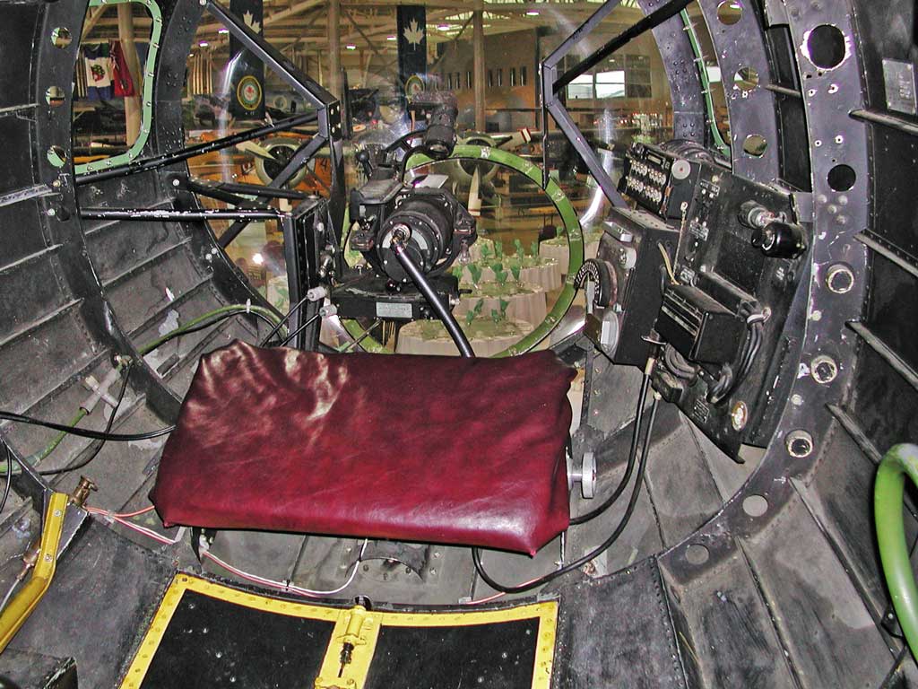
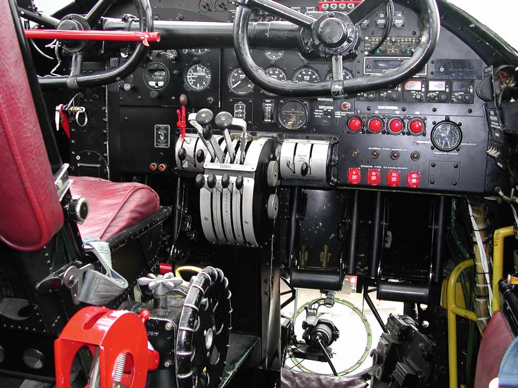
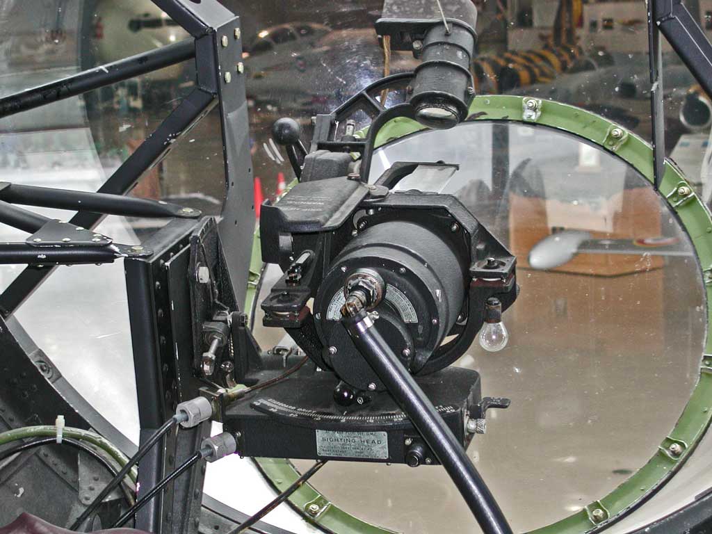
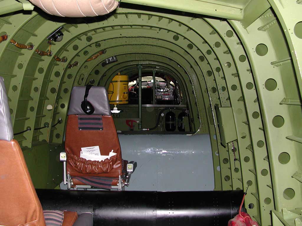
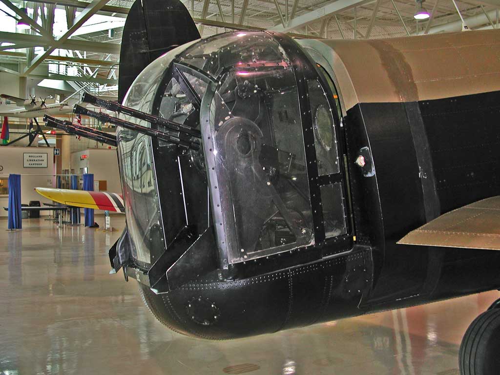
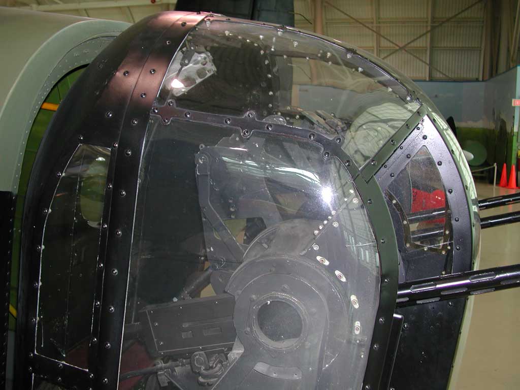
Working with the navigator to know the target position, and the aircraft's height and velocity, and other factors such as the wind would determine the right time to drop a bomb (there would be a bombsight computer to the bomb aimer's left to assist with this).
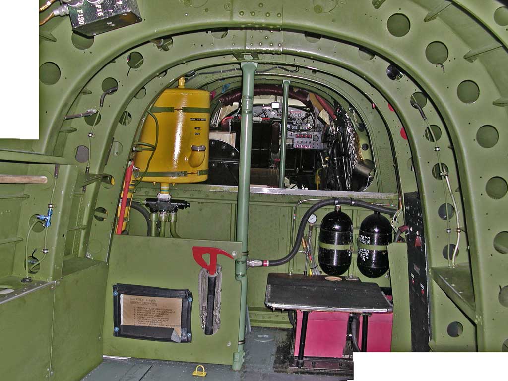
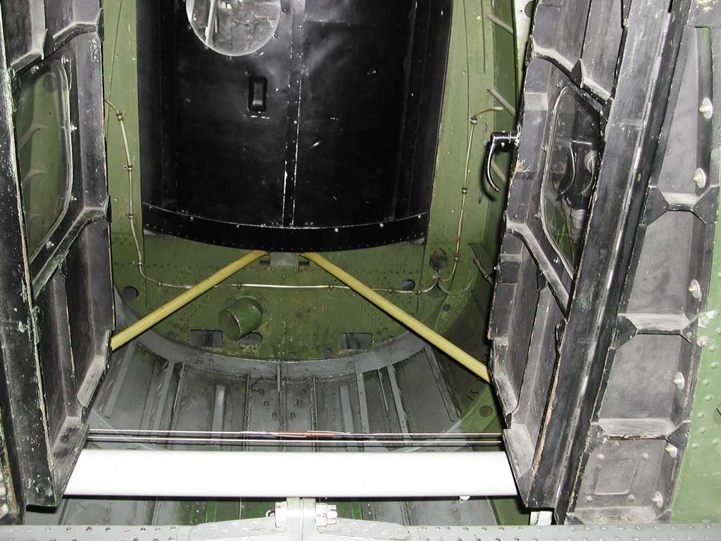
Outlined in yellow, you can also see the nose parachute exit (you'd want to make sure those latches are secure).
Photograph 17 of 83
Photograph 18 of 83
Photograph 19 of 83
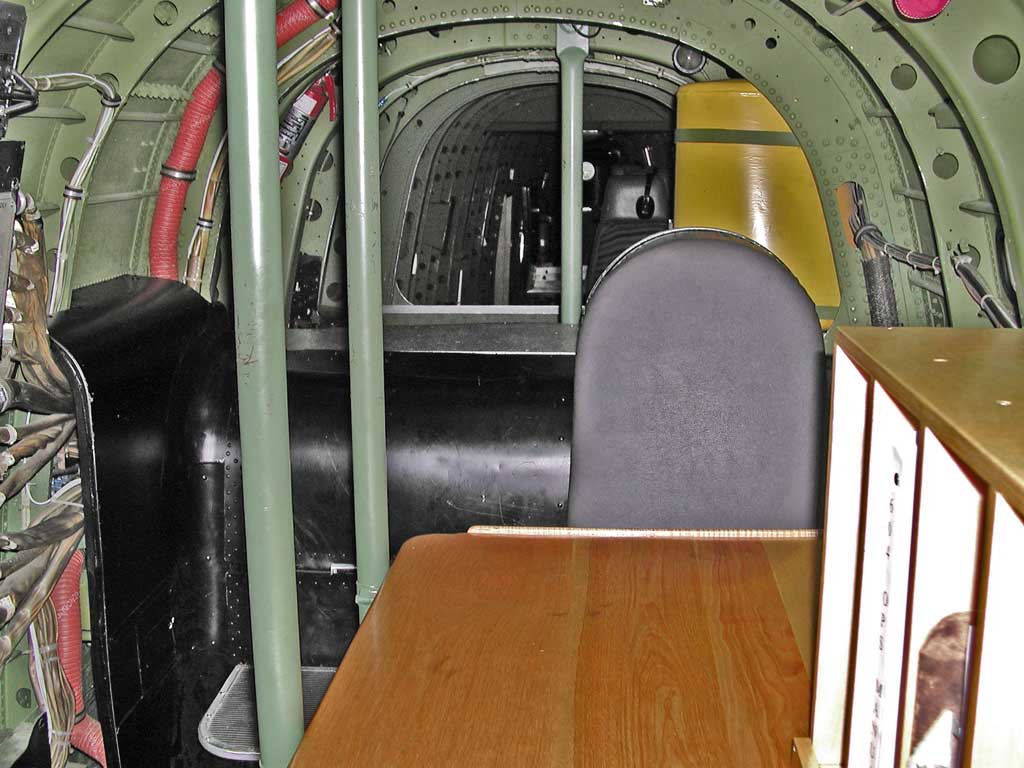
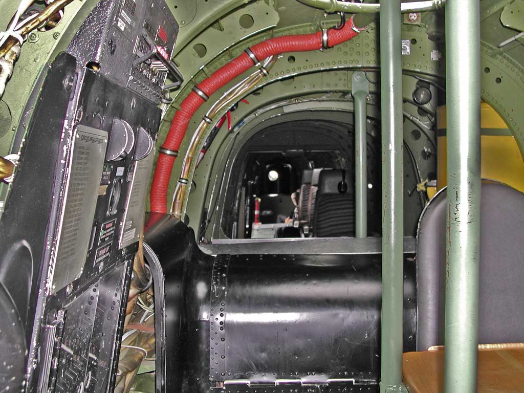
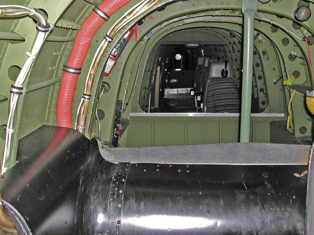
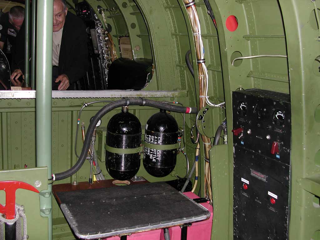
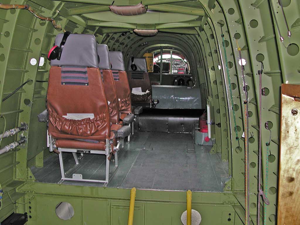
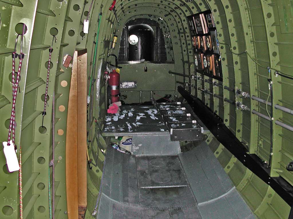
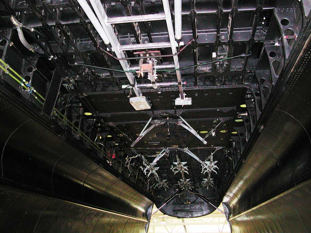
The aircraft's radio would be mounted at the far end of this table, and the wireless operator would sit in the seat at the end of the table, facing frontwards.
The wing's main spar is inside the huge hump behind the wireless operator's seat (the wings aren't just glued onto the side of the plane, the wing's main structural member passes through the aircraft).
Photograph 20 of 83
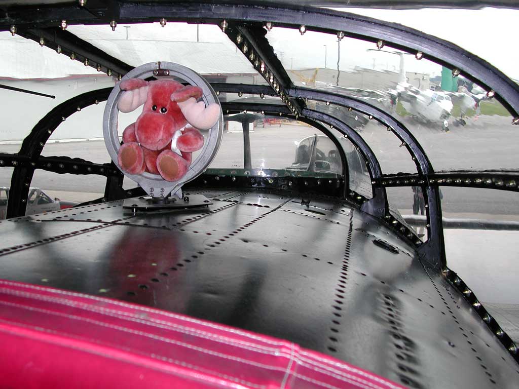
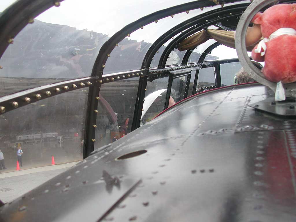
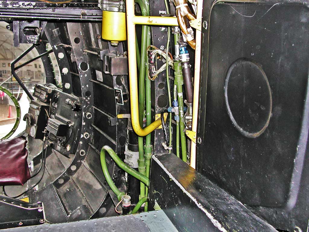
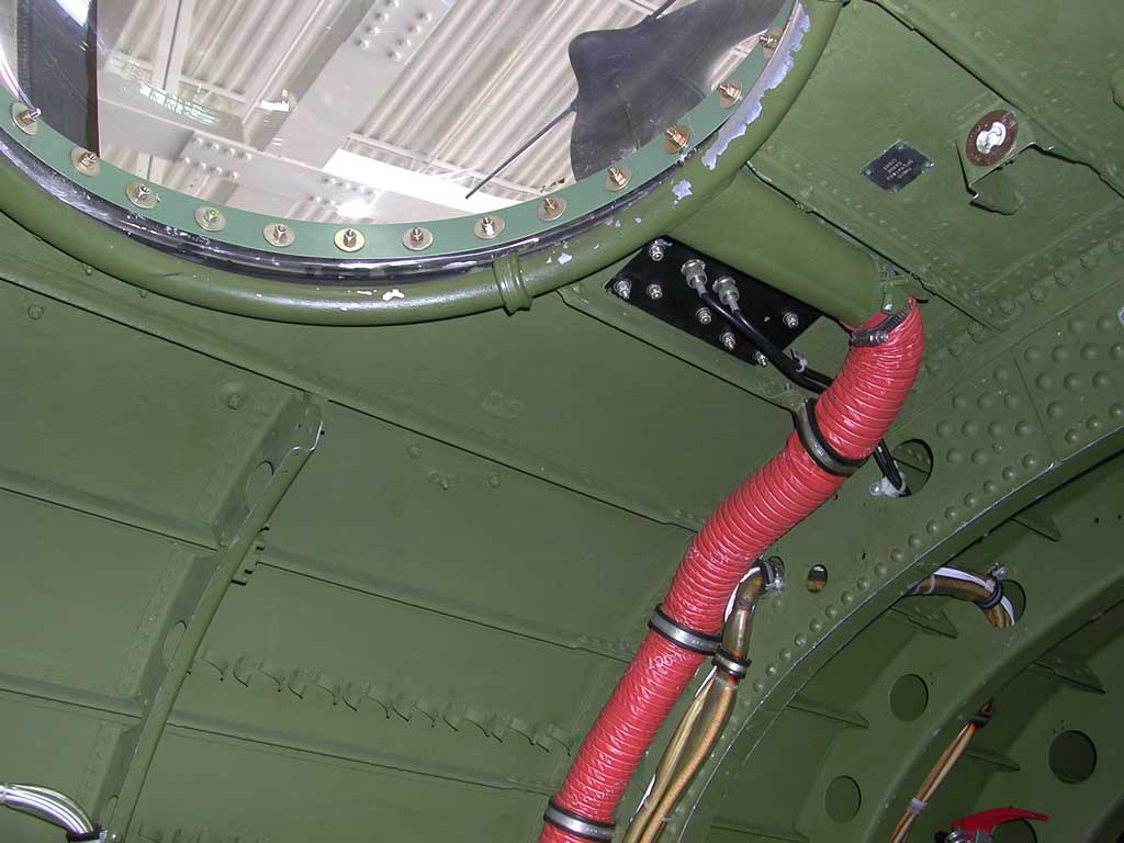
The red hose carries warm air from the engines to heat the clear astrodome, which would be used by the navigator for celestial navigation.
Photograph 21 of 83
Photograph 22 of 83
Photograph 23 of 83
These photographs were all too light in the foreground, and too dark in the distance. Adobe Photoshop's “Shadow/Highlight” tool did an amazing job of compensating for this.
Photograph 24 of 83
Photograph 25 of 83

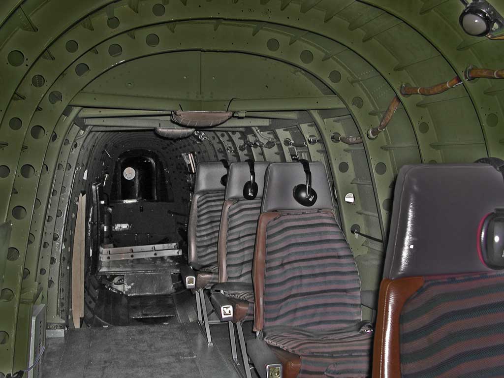
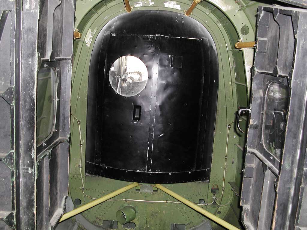
At the very back, you can see the round window to the tail gunner's position.
Photograph 26 of 83
Photograph 27 of 83
Photograph 28 of 83
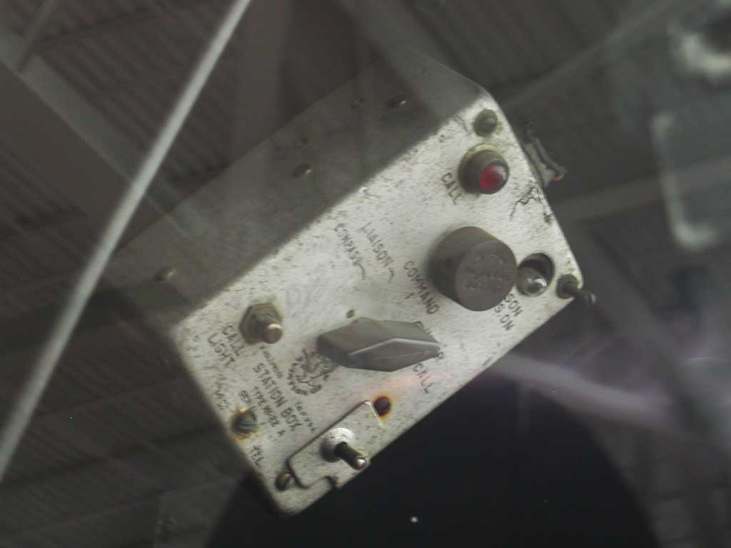
Duct-taped to the left of the red firefighting axe are the aircraft's:
Photograph 29 of 83
Photograph 30 of 83
Photograph 31 of 83
Photograph 32 of 83
Photograph 33 of 83
This, and the tail gunner's positions were not heated, and the gunners would therefore wear electrically-heated suits for the long missions (often 8 hours or more).
Photograph 34 of 83
Photograph 35 of 83
Photograph 36 of 83
Photograph 37 of 83
Photograph 38 of 83
Photograph 39 of 83
Photograph 40 of 83
Notice the bright red pitot tube covers (with a long flag to ensure they will be noticed and not left on for flight). These ensure that bugs don't take up living in the pitot tubes (which aim frontwards and measure air pressure to indicate airspeed).
Photograph 41 of 83
Photograph 42 of 83
Photograph 43 of 83
Photograph 44 of 83
Photograph 45 of 83
Photograph 46 of 83
Photograph 47 of 83
Photograph 48 of 83
Photograph 49 of 83
Photograph 50 of 83
Photograph 51 of 83
Under the picture of the rear gunner's turret, you refer to the guns having great vertical range, “but do not appear to have much side-to-side motion”. In fact, they had about 180 degrees horizontal movement because the turret itself was rotatable. If he had to bale out, the rear gunner would merely rotate hs turret fully to one side and drop out – once he had retrieved his parachute from its storage just inside the rear of the fuselage, of course!
For more about Arthur Spencer, who served in the same Squadron as Clifford, see the Remembrances section.
Photograph 52 of 83
Photograph 53 of 83
Photograph 54 of 83
Photograph 55 of 83
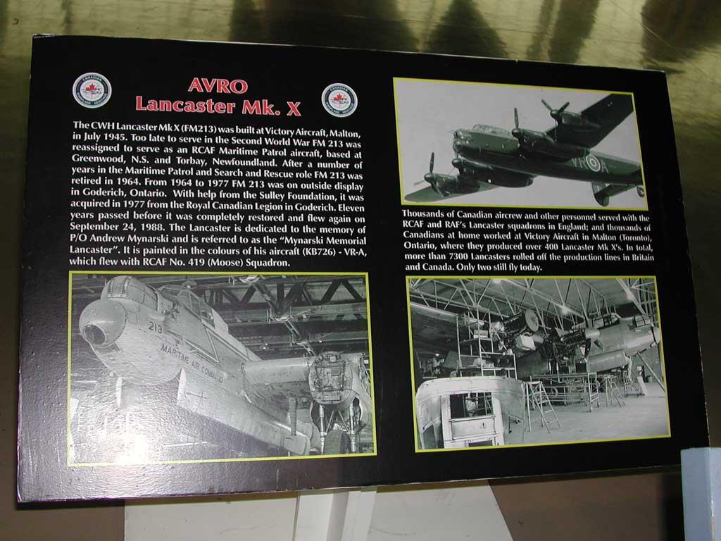
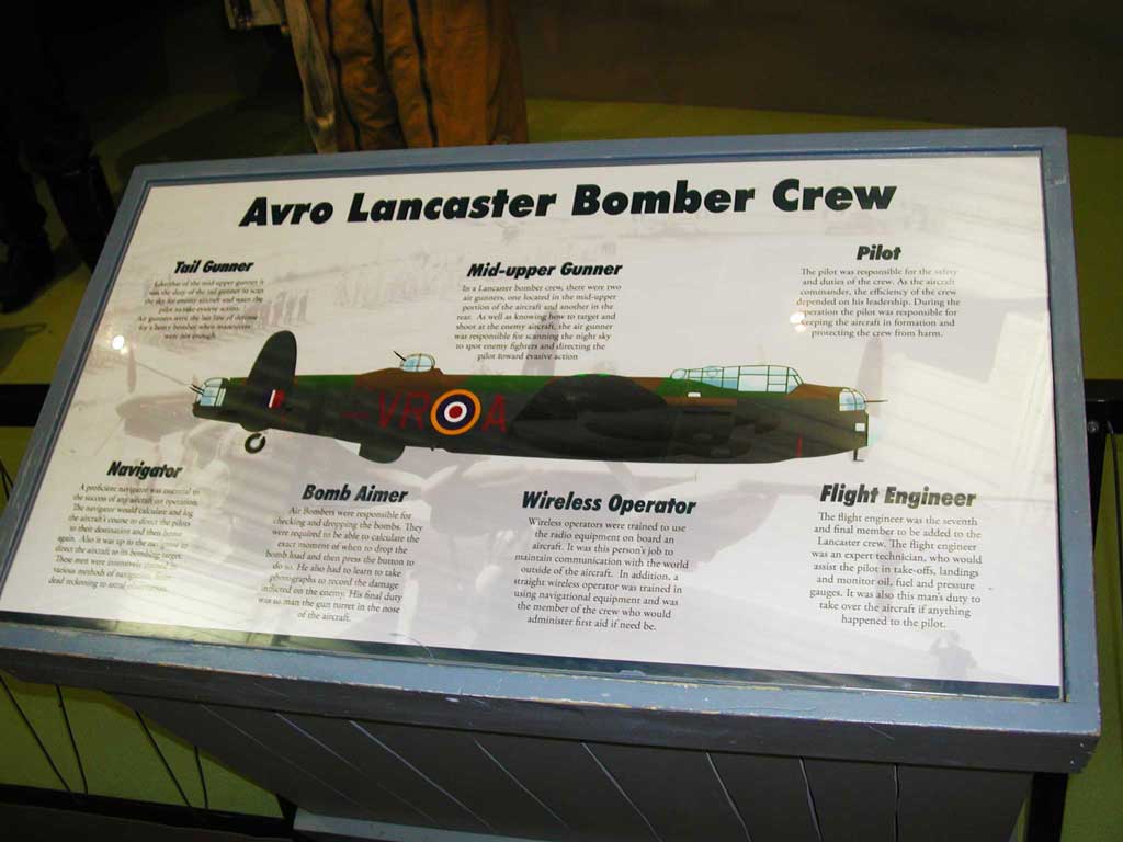
AVRO Lancaster Mk. X
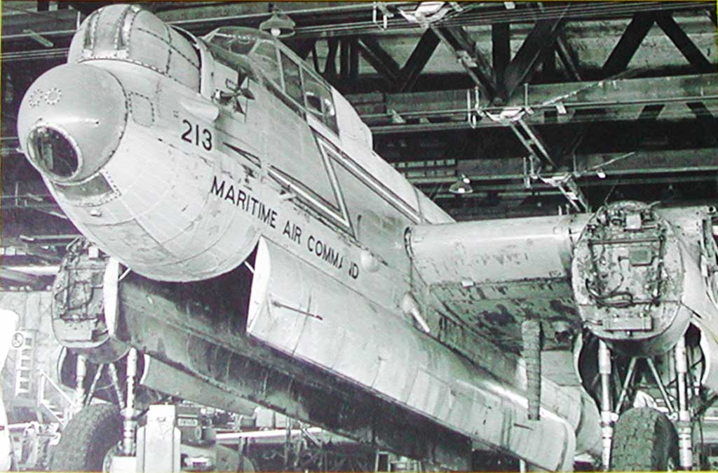
The Canadian War Heritage Museum Lancaster Mk. X (serial number FM 213) was built at Victory Aircraft, Malton, in July 1945. Too late to serve in the Second World War, FM 213 was reassigned to serve as an RCAF Maritime Patrol aircraft, based at Greenwood, Nova Scotia, and Torbay Newfoundland. After a number of years in the Maritime Patrol and Search and Rescue role, FM 213 was retired in 1964. From 1964 to 1977 FM 213 was on outside display in Goderich Ontario. With help from the Sulley Foundation, it was acquired in 1977 from the Royal Canadian Legion in Goderich. Eleven years passed before it was completely restored and flew again on September 24, 1988. The Lancaster is dedicated to the memory of Pilot Officer Andrew Mynarski and is referred to as the “Mynarski Memorial Lancaster”. It is painted in the colours of his aircraft (KB726) – VR-A, which flew with RCAF No. 419 (Moose) Squadron.
Thousands of Canadian aircrew and other personnel served with the RCAF and RAF's Lancaster squadrons in England; and thousands of Canadians at home worked at Victory Aircraft in Malton (Toronto), Ontario, where they produced over 400 Lancaster Mk. X's. In total, more than 7300 Lancasters rolled off the production lines in Britain and Canada. Only two still fly today.
Photograph 56 of 83
Photograph 57 of 83
Photograph 58 of 83
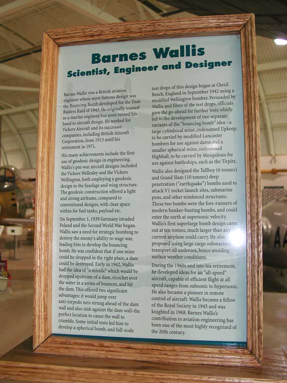
Barnes Wallis
Scientist, Engineer and Designer
Barnes Wallis was a British aviation engineer whose most famous design was the Bouncing Bomb developed for the Dam Busters Raid of 1943. He originally trained as a marine engineer but soon turned his hand to aircraft design. He worked for Vickers Aircraft and its successor companies, including British Aircraft Corporation, from 1913 until his retirement in 1971.
His many achievements include the first use of geodesic design in engineering. Wallis's pre-war aircraft designs included the Vickers Wellesley and the Vickers Wellington, both employing a geodisic design in the fuselange and wing structure. The geodesic construction offered a light and strong airframe, compared to conventional designs, with clear space within for fuel tanks, payload etc.
On September 1, 1939 Germany invaded Poland and the Second World War began. Wallis saw a need for strategic bombing to destroy the enemy's ability to wage war, leading him to develop the bouncing bomb. He was confident that if one mine could be dropped in the right place, a dam could be destroyed. Early in 1942, Wallis had the idea of a “missle” which would be dropped upstream of a dam, ricochet over the water in a series of bounces, and hit the dam. This offered two signifcant advantages: it would jump over anti-torpedo nets strung ahead of the dam wall and also sink against the dam wall – the perfect location to cause the wall to crumble. Some initial tests led him to develop a spherical bomb, and full-scale test drops of his design began at Chesil Beach, England in September 1942 using a modified Wellington bomber. Persuaded by Wallis and films of the test drops, officials gave the go-ahead for further tests which led to the development of two separate variants of the “bouncing bomb” idea – a large cylindrical mine, codenamed Upkeep, to be carried by modified Lancaster bombers for use against dams and a smaller spherical mine, codenamed Highball, to be carried by Mosquitoes for use against battleships, such as the Tirpitz.
Wallis also designed the Tallboy (6 tonnes) and Grand Slam (10 tonnes) deep penetration (“earthquake”) bombs used to attack V1 rocket launch sites, submarine pens, and other reinforced structures. These two bombs were the fore-runners of modern bunker-busting bombs, and could enter the earth at supersonic velocity. Wallis's first superlarge bomb design came out at ten tonnes, much larger than any current airplane could carry. He also proposed using large cargo submarines to transport oil undersea, hence avoiding surface weather conditions.
During the 1960s and into his retirement, he developed ideas for an “all-speed” aircraft, capable of efficient flight at all speed ranges from subsonic to hypersonic. He also became a pioneer in remote control of aircraft. Wallis became a fellow of the the Royal Society in 1945 and was knighted in 1968. Barnes Wallis's contribution to aviation engineering has been one of the most highly recognized of the 20th century.
Photograph 59 of 83
Photograph 60 of 83
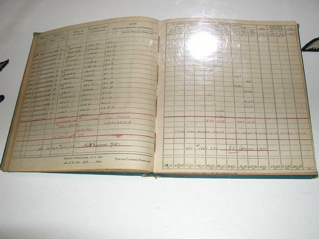
Each column is totaled at the bottom of the page, to be carried forward to the top of the next page's columns (today, “real men” use spreadsheets – in those days, they flew bombers). Above that are totals for the hours of day and night flying.
Photograph 61 of 83
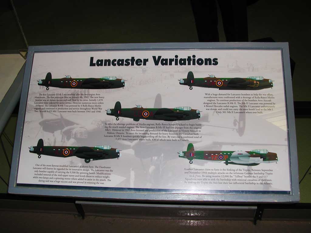
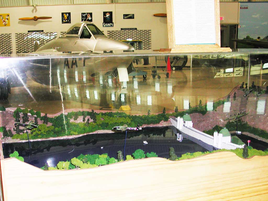
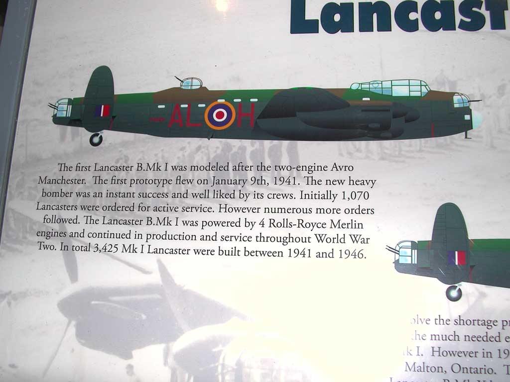
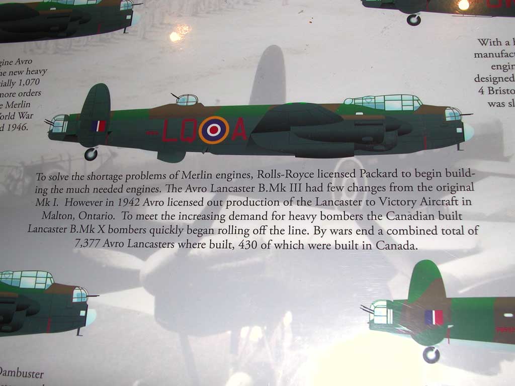
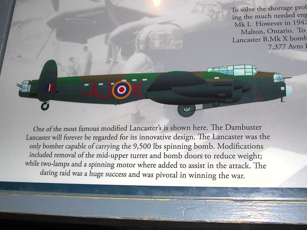
Closer photographs of the original Lancaster (Mark I, top-left), the Mark III (centre), and the dam buster (bottom-left) are below.
Photograph 62 of 83
Photograph 63 of 83
Photograph 64 of 83
Photograph 65 of 83
Photograph 66 of 83
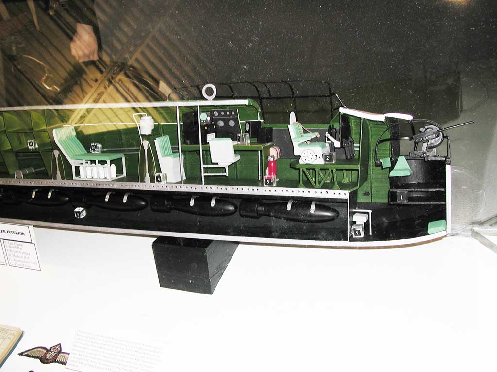
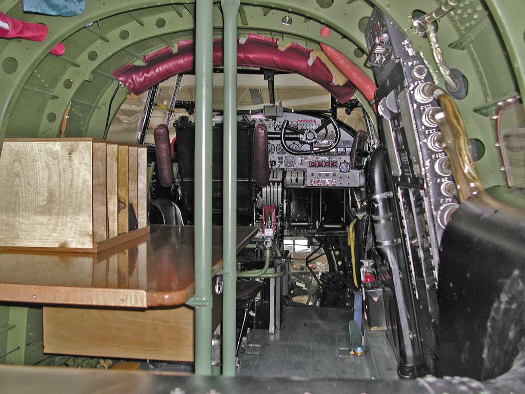
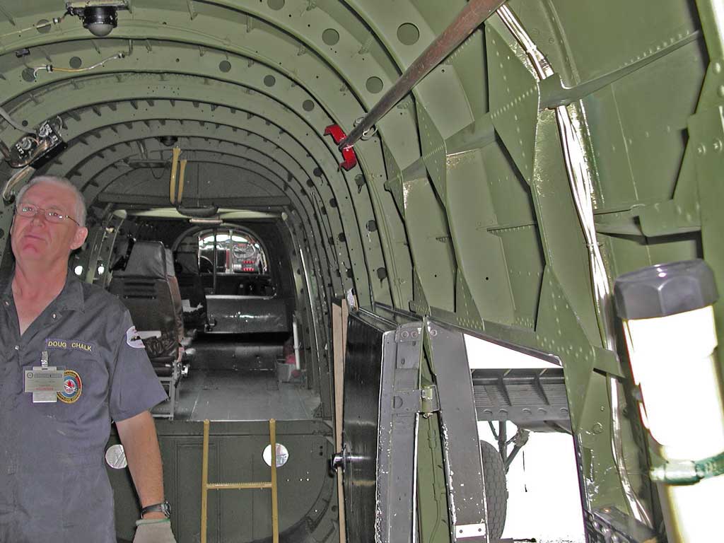
Behind the pilot is the navigator's chair and chart table, and the radio and wireless operator is to his left. Behind the wireless operator is the main spar, the medical bed, and the second wing spar.
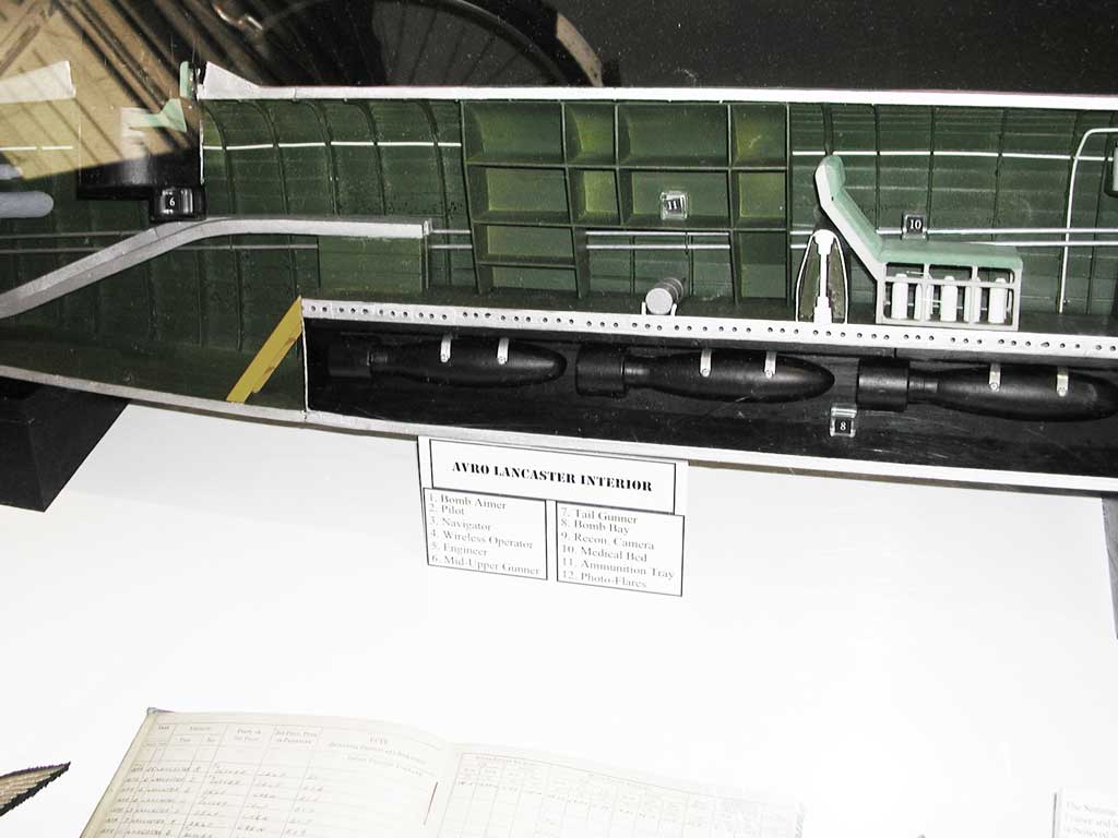
The bomb bay is below.
Photograph 67 of 83
Photograph 68 of 83
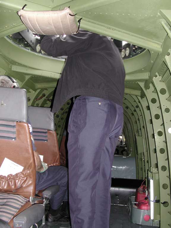
To the aft is the head (after all, it would frequently be an 8-hour mission).
Photograph 69 of 83
Photograph 70 of 83
Photograph 71 of 83
Photograph 72 of 83
Photograph 73 of 83
Photograph 74 of 83
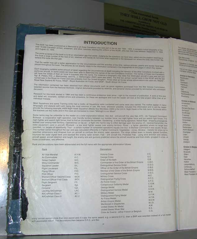
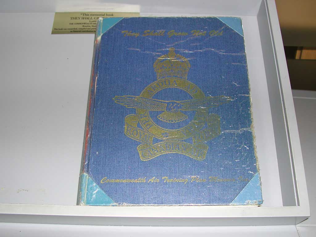
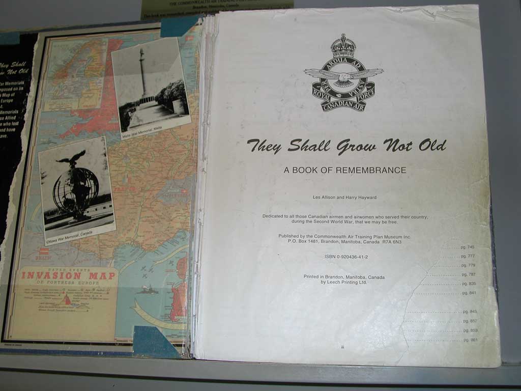
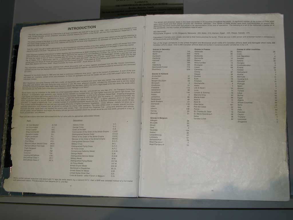
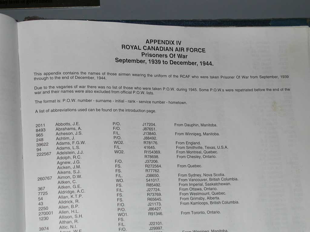
Introduction
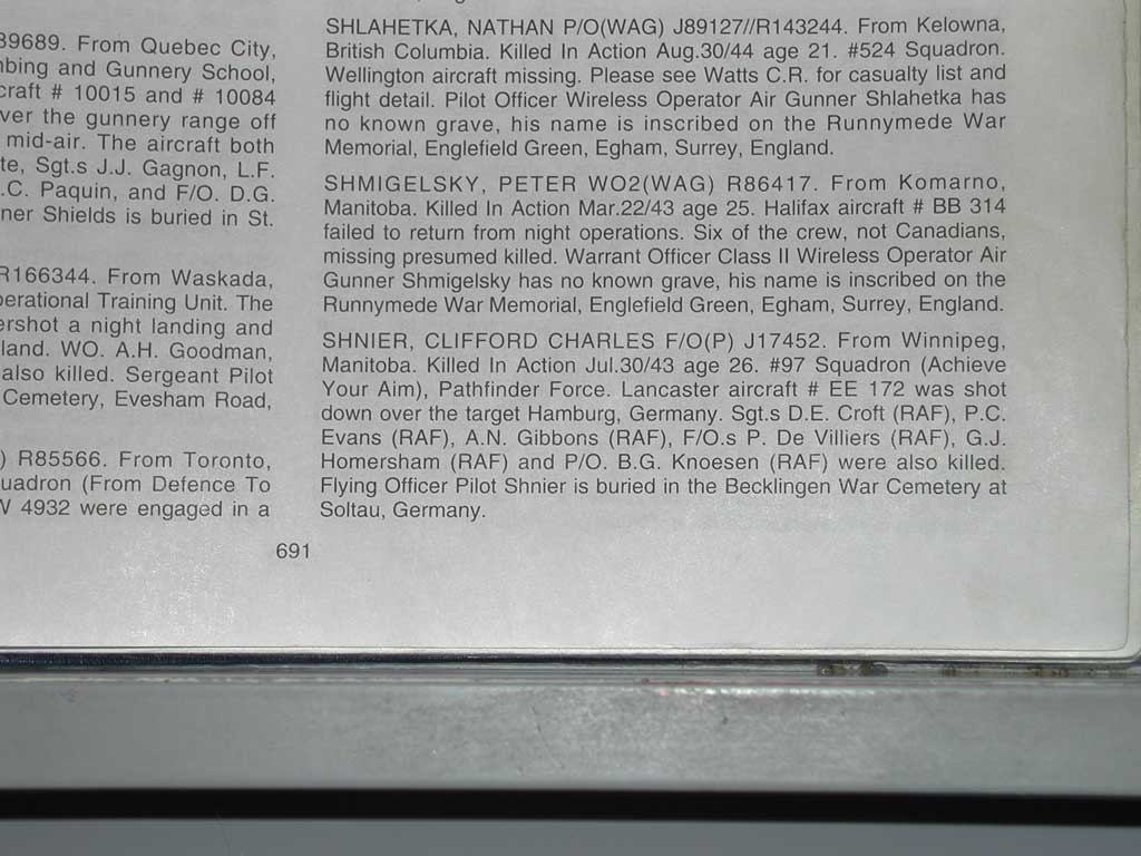
This book has been produced as a Memorial to all those Canadians who took part in the air war 1939 – 1945. It contains a short biography of the over 18,000 Canadian airmen, airwomen, and other nationals wearing the uniform of the RCAF, who lost their lives between September 3, 1939 and August 12, 1945.
The prime purpose of this book is to fill an information gap that exists. Judging by the questions we have been asked and the positive response to this book a large number of the next of kin, relatives and friends do not know what happened to the deceased nor where the body was buried. We believe this book fills that gap.
That the reader may get a better appreciation for the circumstances and the activities of the time, various pictures, poems and stories have been placed throughout the book. The pictures do not directly relate to the information contained in the biographies on the pages in which they appear.
Each biography contains some amount of detail regarding the circumstances at death inlcuding the name(s) of the other Canadians involved with a particular aircraft. In some cases we have been able to determine the names of the non-Canadians involved. The names of these non-Canadians will have the initials of their air force in brackets after the name. For instance a biography may state that Wellington aircraft # xxxx was lost and Sgt. B. Peters, F/O. J. Abercromby, and F/L. J. Heatherington (RAF) were also killed. The first two airmen named were in the RCAF and the last named was in the Royal Air Force and was probably from the United Kingdom. Three other air forces whose abbreviations were used are; RNZAF – Royal New Zealand Air Force, RAAF – Royal Australian Air Force, and SAAF – South African Air Force.
The information contained has been obtained from official documents such as grave registers purchased from the War Graves Commission, selected records from the National Archives, original documents provided by relatives, and personal stories provided by servicemen who witnessed the event.
Research for this book started in 1984 and has been a continuous endevour ever since – right to the moment of publication. A work of this size and detail will, invariably, contain errors and omissions, for these we apologize and trust the reader will look at the total project rather than at an individual mistake.
Most Squadrons and some Training Units had a motto, all Squadrons were numbered and some were also named. The mottos appear in many languages and dialects with Latin being the most common in use. We have, whereever possible, included this information and to aid the reader provide the following example; #409 Night Hawk Squadron (Media Nox Meridies); #409 is the Unit #, Night Hawk is the nick name, the words within the brackets are the motto and in this case are translated to mean “Midnight is our Moon”.
Some terms may be unfamiliar to the reader so a brief explanation follows:
- Ack Ack – anti-aircraft fire, also flak.
- ATC – Air Transport Command.
- Bullseye – a cooperative night operation, over friendly territory between our bomber force, our night fighter force and our search light forces. The night fighter and search light forces tried to find and illuminate the bomber.
- Gardening – a mine laying operation.
- Nickel Raid – dropping propaganda leaflets over enemy-held territory.
- Operation(s) or Op.(s) – a flight into harms way to inflict damage upon the enemy.
- r/t – receiver/transmitter, the radio equipment used in aircraft.
- Rhubarb – a low level fighter sweep over enemy territory.
- Rover – a figher operation where no target was specified, i.e. targets of opportunity.
- Tour – a certain number of completed operations equals one tour. In Bomber Command it was usually 30 ops. The number varied throughout the war and was calculated differently in Fighter Command.
- Vegetables – mines.
- Window – metallic foil strips cut to specified dimensions and dropped from an aircraft to confuse the enemy radar operators. The strips drifted down in loosely spaced bunches, bounced the radar signal back and blanked the enemy radar screen.
- Flak &ndash anti-aircraft fire.
- Predicted Flak – using wind direction and velocity, aircraft speed, aircraft direction and height, the enemy ack-ack gunners predicted where the aircraft would be and fired shells, grouped in a box, at those co-ordinates, very effective.
The page continues with miltary ranks and their abbreviations (such as Pilot Officer – P/O), and military decorations and their abbreviations.
Photograph 75 of 83
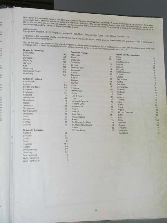
The airmen and airwomen listed in this book are buried in 75 countries throughout the world. A significant number of the bodies of those killed were never found and their places are, therefore, unknown. The names of these airmen have been commemorated on several War Memorials that were constructed and placed to be representative of the area of operations. The following is a list of the memorials, a partial list of the cemeteries, and the number of Canadians listed at each.War Memorials:
- Runnymede, England – 3,125
- Singapore, Malayasia – 200
- Malta – 310
- Alamein, Egypt – 225
- Ottawa, Canada – 470
Casualties in Canada were usually returned to their home provinces for burial. There were over 2,000 airmen and airwomen buried in cemeteries in all the provinces and territories.
Two of the larger cemeteries in the United Kingdom are Brockwood which holds 670 Canadian airforce dead and Harrogate which holds 666 Canadian airforce dead. Over 2,000 Canadian airforce dead are buried in smaller cemeteries in the U.K.
The page continues by listing the number of Canadians buried in cemeteries in other countries, and noting that there are 145 Canadians buried in the Becklingen (which the book spells Becklington) cemetery, as is Clifford Shnier.
Photograph 76 of 83
Photograph 77 of 83
Photograph 78 of 83

Photograph 79 of 83
Photograph 80 of 83
Norman Shnier passed away July 12, 2007, at the age of 87. His memoirs are on this web site here, and obituary in the Remembrances section here.
Photograph 81 of 83
Photograph 82 of 83
Photograph 83 of 83